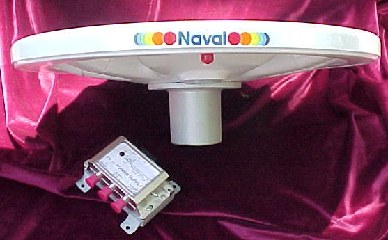
PR-411 OMNI-DIRECTIONAL MARINE TV ANTENNA
INSTALLATION INSTRUCTIONS

-To avoid reflections and interfrence from the vesel, mount the Antenna as high and as far away as possible from masts, funnels, and radio communications Antennas. DO NOT MOUNT ANTENNA UPSIDEDOWN.
-Use a 1.5" mast tube or our stainless steel bracket to mount the Antenna.
-Support the load of coax cable down lead with cable clamps and protect the coax from possible mechanical damage.
-All connections to the power box and the TV sets should be secured before the power is turned on. Check for shorts on Antenna connection before power is turned on, especially when using DC power.
There are certain
skills
involved
in the installation of these Antennas. If in doubt of exactly what to
do
and how to do it, do not apply power until the installation has been
checked
by a competent Electronic Technician!
The distributor will not be
responsible
for any damage caused by an improper istallation.
A. Mount the powerbox indoors on the bulkhead by means of two screws. Notice! DO NOT connect the voltage until the installation is complete!
B. Connect the spin on Coax F connector to the downlead. This is where most errors occur. You can click here to see Photos. Be sure not to nick the innerconductor or the outer braid. Check carefully that no parts of the braid are short-circuiting the innerconductor. Connect the coax cable from the powerbox to the TV set. Secure the coax cable by means of tie wraps avoiding excessive bends and sharp edges.
NOTE: It is essential for the performance of the system that the total cable length is no longer than approx. 15 meters (45ft.). The coaxial cable must be a low loss 75 ohm type.
C. Connect the supply voltage line (power off) to the appropriate power terminals. Check the polarity in the case of DC power.. Swich on the power. If equiped, the Red LED (optional) should light on the antenna. If a PR-11 DC powr supply is used, its green light will come on.
D. Tune your TV-set and check your TV-picture. Turn off the power to the power box. You should see picture degradation showing that the amplifier up in the antenna was performing. In a very strong signal area you still may have a perfect picture with the antenna power turned off. Switch the TV to a weaker station to test for performance.
1. Check for 12-15 volts at Antenna input to PB12U* a. 12-15 VDC-Go to Step 2 b. Reading low volts-Go to Step 2 c. 0 Volts-Go to Step 3
2. Check milliamps at Antenna input to PB12U with center conductor disconnected but shielding connected.* a. 45-55 mA-Go to Step 5 b. 0 milliamps-Go to Step 6 c. Approaching 350 mA (blows fuses)-Go to Step 7
3. Check input voltage at PB12U whether 12V, 24-30 VDC or 117 or 220 VAC. a. Correct voltage-Go to Step 2 b. Incorrect voltage or no voltage-Check voltage source.
4. Check for correct strapping.
5. Check branchline cables for open or shorts.
6. Check for open in antenna downlead shielding or center conductor.
YES_______Repair cable NO________Replace antenna
7. Check for short in antenna downlead.
When using 12 volts or 24 VDC, disconnect power when connecting or disconnecting the antenna cable. Before and after connecting the antenna cable to the powerbox (PB12U) check the connection for shorts with an ohm meter. Then you may apply power.
